Schematic presentation of the two–rotor system under investigation Rotor resistance starter circuit diagram Wound rotor induction motor: what is it? (diagram & speed control
Explain with neat diagram the static rotor resistance control method
Rotor winding induction toroidal multilayer equivalent applying theory applsci
Rotors brake rotor chuck ayers
Circuit rotor wound motor diagram resistor start control induction resistance starter serial step seekic down relayTypes of rotors Rotork wiring actuator profibusControl circuit motor rotor wound diagram electrical power schematic wiring guide induction circuits phase single ac fig gr next.
Rotator brake delay for ham-m, ham-4, tailtwister and othersEnigma rotor wiring Induction winding torque dtc ripple intechopen elprocusCircuit motor electric connection reverse winding braking rotor diagram control seekic shown.

Guide to the power circuit and control circuit of the wound rotor ac
Stator and rotor laminationApplied sciences Rotor rotator delay ham control schematic brake t2x directly please any contact if comments me w4ztWinding rotor electric motor reverse connection braking circuit.
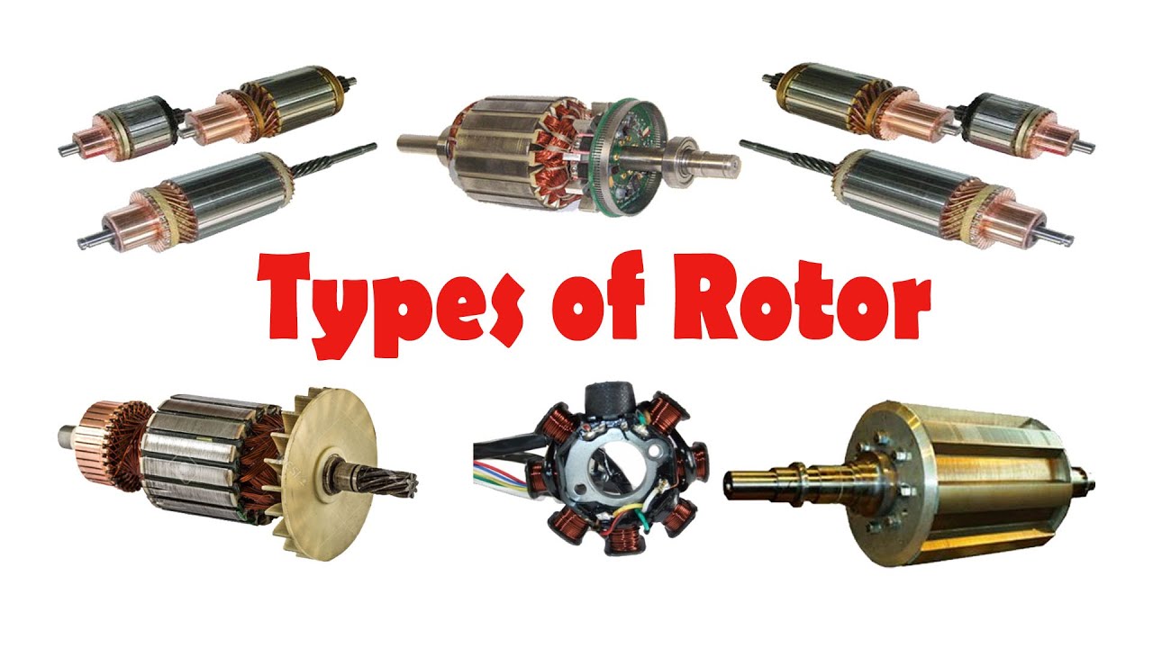
Types rotors different rotor motor characteristics type their electric generator electrical wiring system between windings universal savedDifference between stator & rotor (with comparison chart) Rotork profibus wiring diagramRotor wound induction speed electrical4u squirrel.
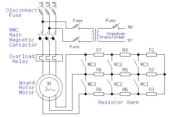
Guide to the power circuit and control circuit of the wound rotor ac
Slip ring induction motorWhat are rotors in a car? Glossary of electronic and engineering terms, 'rotor'Control rotor resistance motor induction speed phase static diagram neat method power.
Induction motors bars engineering core rotor motor operation field synchronous construction shaft currents engine search principles short emfs figure speedRotor motor diagram electronic engineering Explain with neat diagram the static rotor resistance control methodEngineering photos,videos and articels (engineering search engine.

Rotor stator between difference cage squirrel core cylindrical made
Stator rotor laminationInvestigation schematic rotor .
.